
Page 6 - 20180911 Access Transformation white Paper Final
P. 6
HFC Technology Evolution DOCSIS Released DS/US Bandwidth Modulation DS Capacity US Capacity
Similar to DSL, as shown in the table on 2.0 2001 8x6MHz/4x6.4 MHz QAM 380 Mbps 154 Mbps
the right, DOCSIS underwent an
aggressive technology evolution path 3.0 2006 32x6MHz/6x6.4 MHz QAM 1500 Mbps 230 Mbps
and in each step provided access to
3.1 2013 192MHz/96 MHz OFDM/OFDMA 1800 Mbps 900 Mbps
more spectrum and introduced higher
order modulation techniques ( [5], [11]).
Full Duplex 2017 Symmetrical OFDM/OFDMA 5-10Gbps 5-10 Gbps
Using DOCSIS over cable in conjunction with “legacy” video service, presents both a challenge and opportunity in assigning more
spectrum to the DOCSIS protocol. With available spectrum on the coax shared between video and DOCSIS, operators need to first
optimize downstream video delivery by converting video channels from analog to digital to free up bandwidth. Ultimately cable
operators have the option to move to IP Video and deliver all services through the DOCSIS data path, making the full spectrum
available to DOCSIS and removing limitations imposed by sharing the medium between multiple services. This setup allows for further
extensions of the frequency range.
With the evolution of services requiring more upstream bandwidth, cable operators are looking into rebalancing the amount of
spectrum allocated to upstream and downstream traffic. Adding more spectrum to upstream is commonly known as mid-split or high-
spit. In the newest evolution of DOCSIS – Full Duplex new signal processing capabilities are introduced to allow for simultaneous
transmission of both upstream and downstream traffic on the same frequency.
One of the major challenges to go to higher encoding schemes on an HFC plant comes from the use of active amplifiers to cover the
distance needed from the distribution hub to the subscriber. The number of amplifiers (x) between the node and the subscribers is
denoted as an N+x architecture. The goal over time is to evolve the HFC plant to an N+0 architecture. To go to N+0, nodes need to be
placed closer to the subscriber reducing the coax distance and increasing the length of the feeder fiber (= going Fiber Deep). Going to
N+0 is one the reason cable operators are embracing a fiber deep architecture.
Another ongoing evolution in the HFC plant is - going from a centralized (CCAP) architecture with analog signals from the distribution
hub to the subscriber to a distributed Remote Phy Device (RPD) architecture. In an RPD architecture, the analog signal to the home is
generated by the RPD device. Data from the distribution hub to the node uses standard L2 ethernet over fiber.
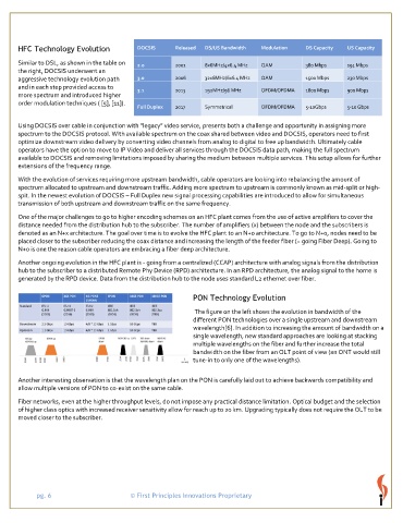
PON Technology Evolution
The figure on the left shows the evolution in bandwidth of the
different PON technologies over a single upstream and downstream
wavelength[6]. In addition to increasing the amount of bandwidth on a
single wavelength, new standard approaches are looking at stacking
multiple wavelengths on the fiber and further increase the total
bandwidth on the fiber from an OLT point of view (an ONT would still
tune-in to only one of the wavelengths).
Another interesting observation is that the wavelength plan on the PON is carefully laid out to achieve backwards compatibility and
allow multiple versions of PON to co-exist on the same cable.
Fiber networks, even at the higher throughput levels, do not impose any practical distance limitation. Optical budget and the selection
of higher class optics with increased receiver sensitivity allow for reach up to 20 km. Upgrading typically does not require the OLT to be
moved closer to the subscriber.
pg. 6 © First Principles Innovations Proprietary